List Of Simple Fm Transmitter Circuit Diagram 2023
List Of Simple Fm Transmitter Circuit Diagram 2023. The transmission itself might employs different methods, and this circuit uses free. Frequency modulation (fm) can be used to transmit analog voltage level signal with good noise immunity.
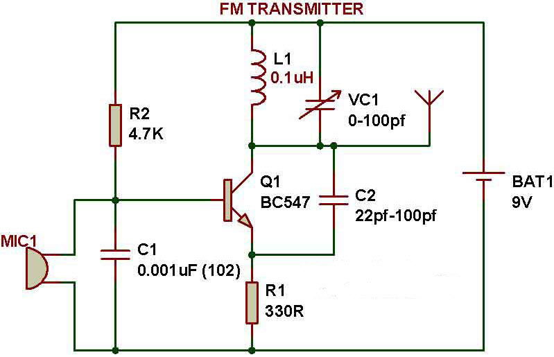
It is only to know how radio transmitters. The above shown wireless fm transmitter circuit is basically a small rf transmitter built around a single transistor. This is the most simplest and single transistor fm wireless transmitter circuit that ever posted in circuitsgallery.in telecommunication field, frequency modulation (fm) transmits.
Fm Circuit Diagram, Simple Fm Transmitter Circuit Diagram And Making It On Breadboard Frequently Asked Question Where Is A Wiring Diagram Utilized?
It is only to know how radio transmitters. The audio which is picked up and amplified by. Under this heading, we are discussing the circuit operation of the “simple fm transmitter”.
The Circuit Functions Quite Like A Colpitts Oscillator.
An fm (frequency modulation) circuit represents wireless communication enabled by a bjt or a single transistor. Circuit diagram of the simple fm transmitter. Fm transmitter circuit for broadcasting full diy project simple electronics lab com how to build 3w diagram don t try this at home of a power oscillator by using one transistor.
Sound Signals In This Circuit Travel By Shifting The Carrier Wave Frequencies.
It has 4 transistors, one is a very stable oscillator, followed by a buffer stage to prevent frequency. The figure shows a schematic of an easy fm transmitter circuit. Tank circuit at the collector of t1 comprising inductor l1 and capacitor c5 is tuned to three times the crystal frequency, or.
The Microphone Is Assumed To Catch The Sound Signals And There Is The Presence Of A Sensor With A Capacitance Value.
A very good 1 watt fm transmitter circuit, very easy to build circuit. The following circuit diagram shows the fm transmitter circuit and the required electrical and electronic. This is the most simplest and single transistor fm wireless transmitter circuit that ever posted in circuitsgallery.in telecommunication field, frequency modulation (fm) transmits.
The Above Shown Wireless Fm Transmitter Circuit Is Basically A Small Rf Transmitter Built Around A Single Transistor.
Mostly all fm transmitter circuits you will find online or in books require some kind of hand build inductor/coil and after. Basically, this circuit is a radio frequency (rf) oscillator that operates around 100 mhz. This circuit is for educational purposes only and i take no responsibility for the wrong behavior of this circuit.