Incredible Breadboard Connection Diagram References
Incredible Breadboard Connection Diagram References. You can completely rearrange the layout of the circuit but following the breadboard diagram exactly is the easiest way to get started with building a breadboard. The diagram shows how the breadboard holes are connected.
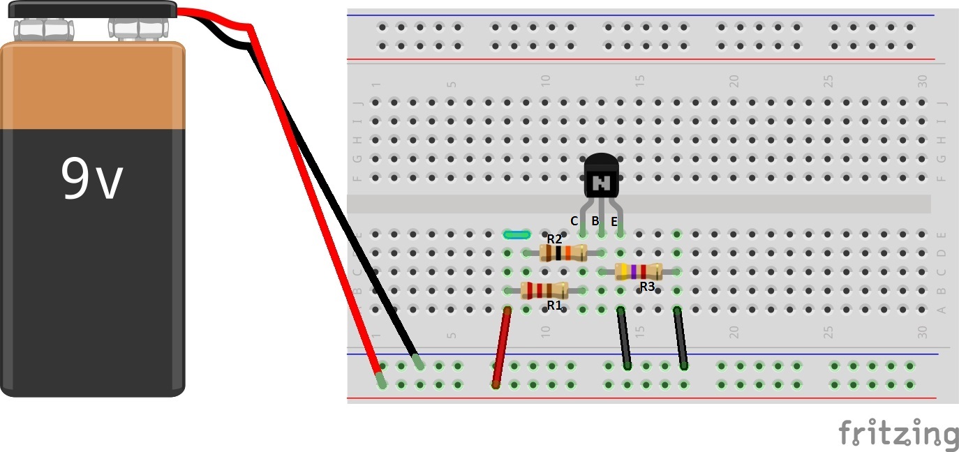
You can completely rearrange the layout of the circuit but following the breadboard diagram exactly is the easiest way to get started with building a breadboard. It is a device having electronics and test circuit designs. Gnd is then connected to the resistor via a green jumper.
It Uses One Of The Bottom Horizontal Connections Or Rails As Gnd.
The purpose of the diagram is to convey. Slide the stripped end of your jumper wire through the hole, and screw the post back down until the wire is firmly connected. Regarding the breadboard connections, they are a little more complex this time due to the fact that the optocoupler housing of the fritzing part i.
The Diagram Shows How The Breadboard Holes Are Connected.
The numbers around the outside are the. The leads of most components can be pushed straight into the holes. It is a device having electronics and test circuit designs.
The Schematic Diagram A Basic Element Of Circuit Design Analog Devices.
After this, both the resistor and led are. Typically, you only need to connect a power and ground wire. You can completely rearrange the layout of the circuit but following the breadboard diagram exactly is the easiest way to get started with building a breadboard.
Schematic · November 17, 2022.
Gnd is then connected to the resistor via a green jumper. Learn how to use a breadboard in minutes breadboards the basics tutorial electronics with raspberry pi magpi. Ne555 the top and bottom rows are linked horizontally all the way across.
A Breadboard Is A Circuit Board That Is Used To Make Temporary Circuits.
Breadboards have many tiny sockets (called 'holes') arranged on a 0.1 grid. Connect the 100uf capacitor’s positive lead to the 555 ic’s pin six and the opposing end to the bottom power rail. Breadboard basics and connections what is breadboard?